| Family |
Select the compound part family from which to edit the compound part. |
| Name |
Displays the name of the compound part being edited. |
| Description |
Contains the description of the new compound part being edited. |
| Sample Height |
Fixed Height parts are relative to the bottom of wall plane. Variable Height parts are relative to the Height setting in the placement tool, at the time the wall is placed. Sample Height corresponds with that setting. Sample Height lets you test your compound wall to make sure it responds the way you intended. |
| Total Height (display only) |
Displays the calculated total height measurement of the compound part as currently defined. |
| Total Thickness (display only) |
Displays the calculated total thickness measurement of the compound part as currently defined |
| Number of Parts (display only) |
Calculates the total number of parts that comprise the compound part. |
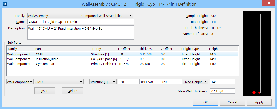
| Sub Parts group box |
The following settings are available.
- Sub Parts list box — Displays the individual parts of the compound part; their dimensions and offset settings.
- Family option menu — Located below the list box Family column. Sets a defined part family, for inclusion as a sub part in the compound part being edited.
- Part option menu — Located below the list box Part column. Sets a defined part, defined within the adjacently-selected Family option menu, for inclusion as a sub part in the compound part being edited.
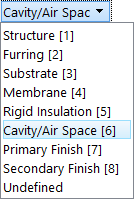
- Priority option menu — The Priority setting controls how compound wall subparts are cleaned up and joined.
The Priority settings each have a numbered priority to them. The priorities at the top of the option menu are more important than those at the bottom of the menu. When compound walls join, the more important subparts are joined first and they are not broken by subparts having a lower priority.
- H Offset field — Located below the list box H Offset column. Sets the horizontal offset (distance) from the line of placement.
- Thickness field — Located below the list box Thickness column. Sets the thickness of the sub part being edited.
- V Offset field — Located below the list box V Offset column. Sets the vertical offset (distance) from the line of placement.
- Height Type — The Height Type option menu sets the height to Fixed or Variable. This setting is used in conjunction with the Height field setting to manage the compound wall variable height feature which enables you to set variable heights for certain compound wall parts while maintaining a fixed height for other parts.
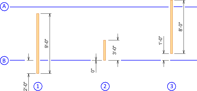
- Fixed Height – When using fixed height, vertical offset can be positive or negative from the bottom of wall. In this case, wall height must be positive and the application uses the absolute wall height value if a user enters a negative value. The image below demonstrates this.
- A: Top of Wall
- B: Bottom of Wall
- 1: Height 9’-0; Vertical Offset -2’-0
- 2: Height 3’-0; Vertical Offset 0’-0
- 3: Height 8’-0; Vertical Offset 1’-0
- Variable Height – When using Variable Height, V Offset can be specified as a positive or negative distance from top of wall. The image below demonstrates this.
- A: Top of Wall
- B: Bottom of Wall
- 1: Height 0’-0; Vertical Offset 0’-0
- 2: Height -1’-0; Vertical Offset -1’-0
- 3: Height 1’-0; Vertical Offset -1’-0
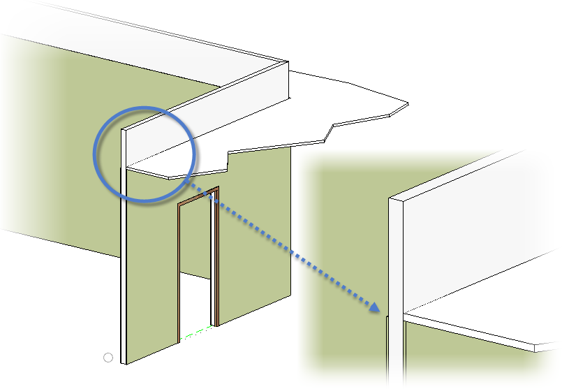
Consider this workflow example: Drop ceilings are common in office buildings. When drop ceilings are designed, the stud walls are often required to go the full distance between floors and the gypsum board (sheet rock) is only required to extend up to the drop ceiling. In this case, you can use the variable wall height feature to specify different heights for the compound wall subparts. Tip: In this example, the compound wall – stud wall subpart – sets the fixed height at 12:0 ft. This is indicated by the Total Height. The compound wall – gypsum board subpart – is set to a variable height of -2:0 ft. This causes the gypsum board to be 10:0 ft high; 2:0 ft lower than the stud wall, at the 10: ft high drop ceiling.
- Height field — Located below the list box Height column. Sets the height of the sub part being edited.
- Insert — Inserts all settings (completed in list box option menus and fields) for the new compound part, sub part, definition into the Sub Parts list box.
- Delete — Deletes the selected sub part from the compound part's definition.
- Main Wall Thickness — Sets the total, combined sum of all sub part thickness' for the compound part.
|
| Compound Part, Sub Parts preview box |
Dynamically updates a graphic display of compound part sub parts as they are edited. |
| OK |
Implements and saves changes, and closes the dialog. |
| Cancel |
Discards changes and closes the dialog. |
| Apply |
Applies changes without dismissing the dialog. |